
Originally Posted by
zombie

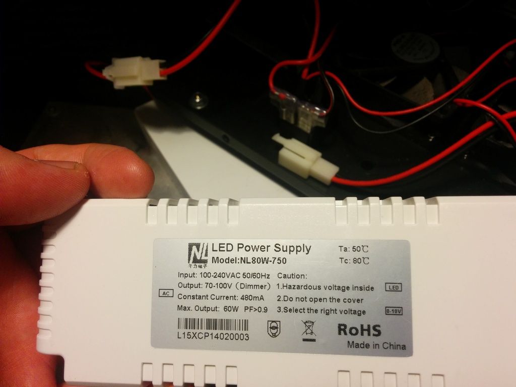
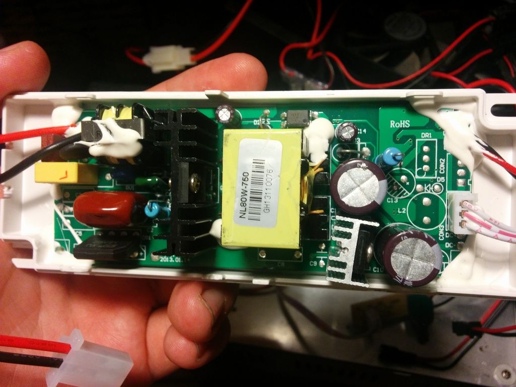
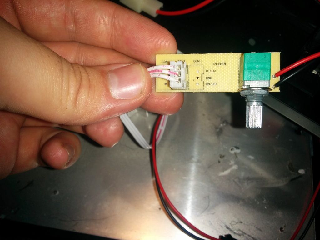
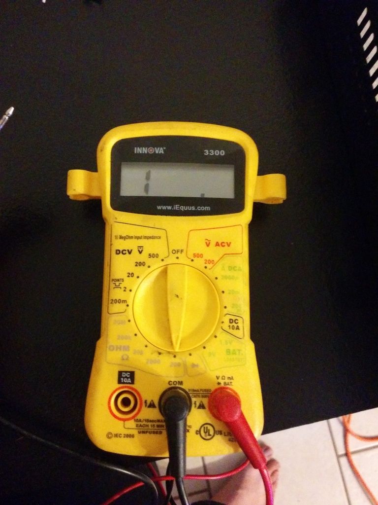
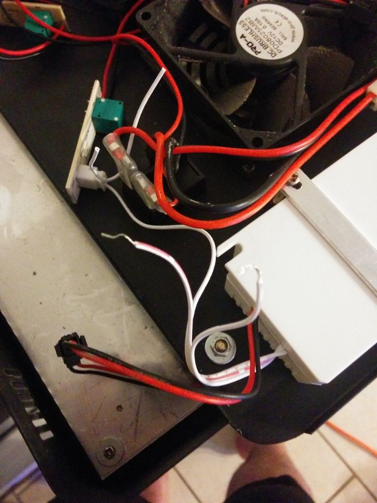
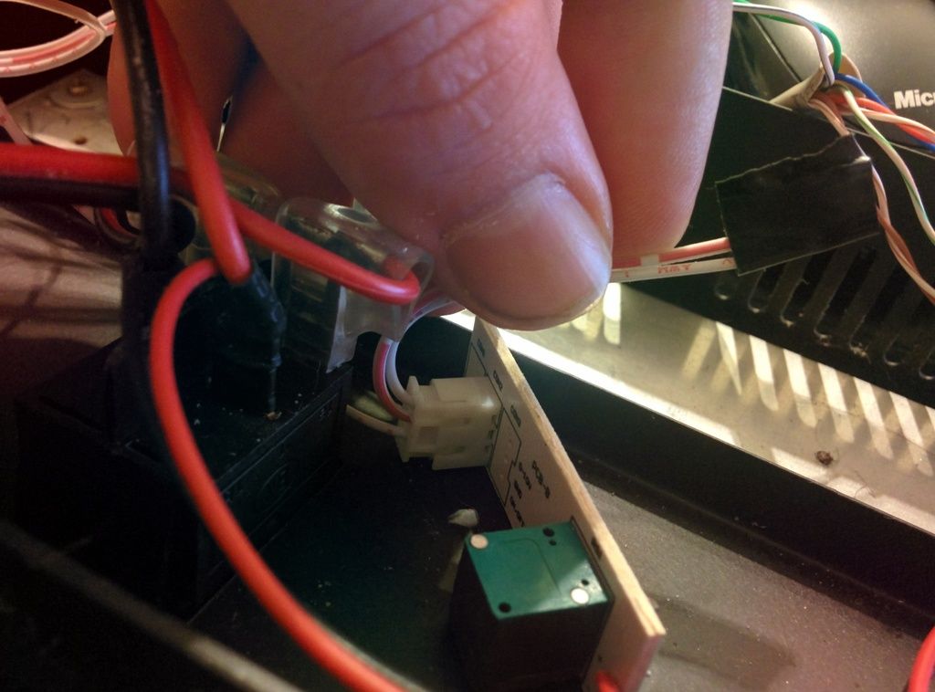
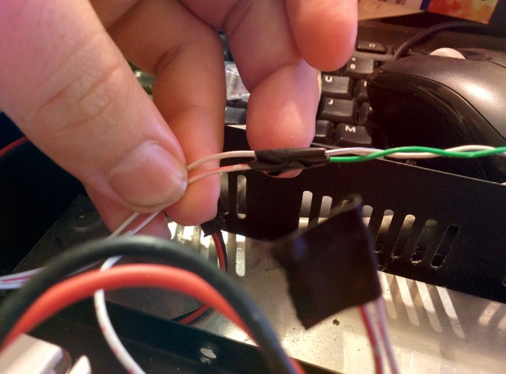
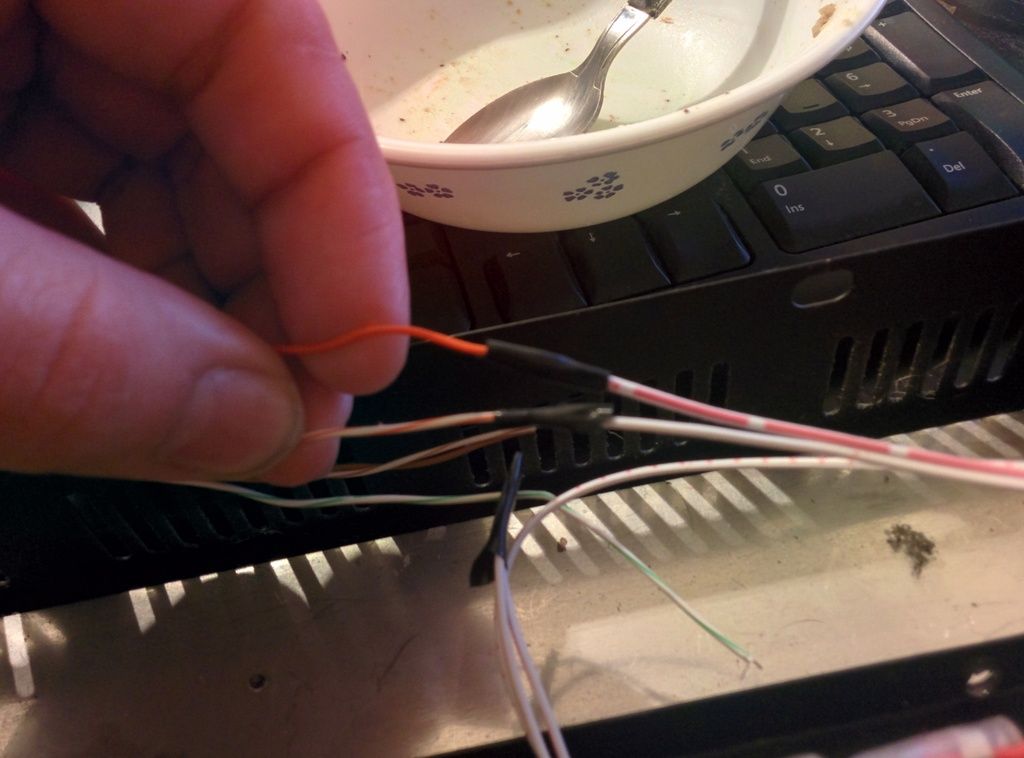
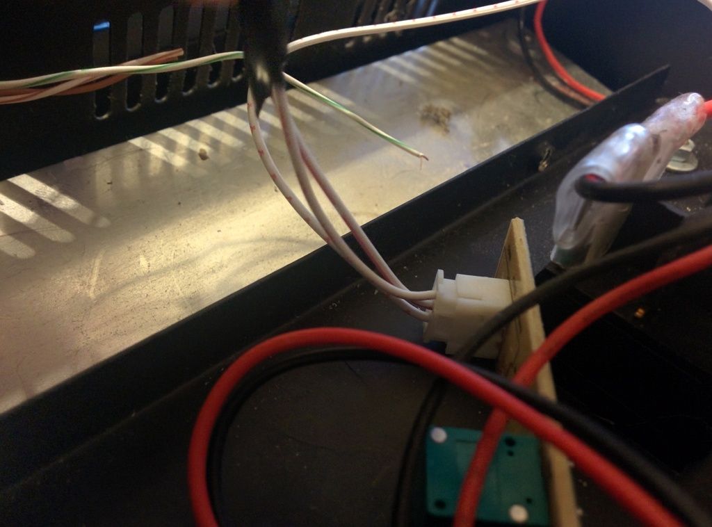
You would need unplug both wires 0-10V and GND from the dimming pot. Then splice V1+ into 0-10V and splice V1- into GND. Before you do that though, can you take a resistance measurement between 0-10V and GND to make sure the VDM won't get damaged by doing so? You may need to have a 3 way node between wherever the GND wire goes, the V1-, and the connection that says GND, but I can be certain without seeing a schematic. Leave enough wire on that connection that you can 3 way splice if need be.


 Reply With Quote


Bookmarks